Carton continuous elevator:
Continuous elevator is used for transporting goods from horizontal direction to vertical direction. Equipped with conveyor lines at the entrances and exits, it can automatically complete the transportation of goods up and down, and can be used for the transportation of goods upstairs and downstairs in factories and logistics centers.
The z-type elevator is the elevator conveying the goods in the "Z" direction, that is, the cargo enters from one side and the output conveying direction from the back side is from bottom to top. Type C elevator is a "C" type elevator, that is, the import and export of cargo transportation are on the same side, and the transportation direction is from top to bottom.
Continuous hoist is a special equipment used for continuous lifting or lowering of unit cargo. Because its chainplate return does not take up the work beat and promotion space, so it has the characteristics of high efficiency, low cost, small occupation space and so on. Compared with the screw chain plate machine, it has a small area, low cost. It is more efficient than a reciprocating elevator.
Applicable conveyors: plastic turnover box, paper packaging, tooling board and hard conveyors with continuous bearing surface on the bottom.
One. main mechanical structure and features:
Body: adopt frame combination structure, mainly composed of upper, middle and lower parts. Adjust the number and length of intermediate frame to meet the needs of different lifting heights. The central column of the frame is made of c-shaped cold-formed sections, which are welded on one side and then bolted to form an independent frame.
Outer sealing frame: wire mesh sealing frame is adopted.
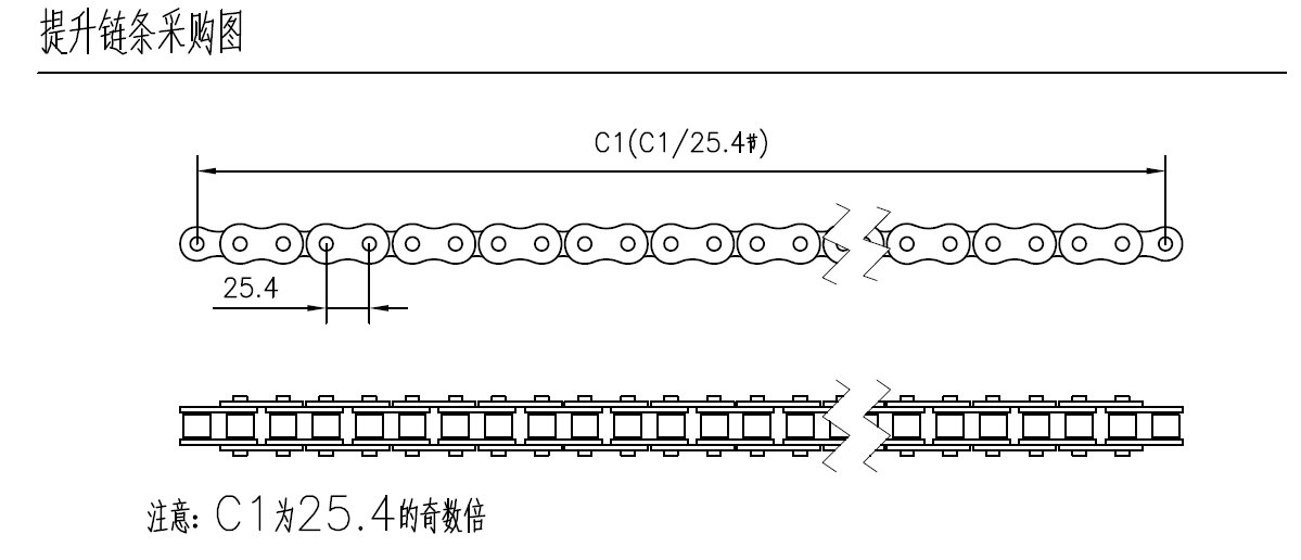
Loading platform: it adopts pallet chain to connect aluminum profiles to form the loading platform. The loading platform is equipped with different u-shaped connectors, which are connected to the lifting chain. As shown in the figure below, the lifting chain runs:
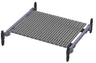
Surface coating: steel wire brush and sandpaper are used to remove rust, acid wash to remove grease. After phosphating, the surface is sprayed with epoxy powder and baked. The thickness of resin is between 60 m and 90 m. Spraying color shall be specified by party a's color card.
Two. Main performance and parameters:
Z-type continuous hoist (cvc-z)
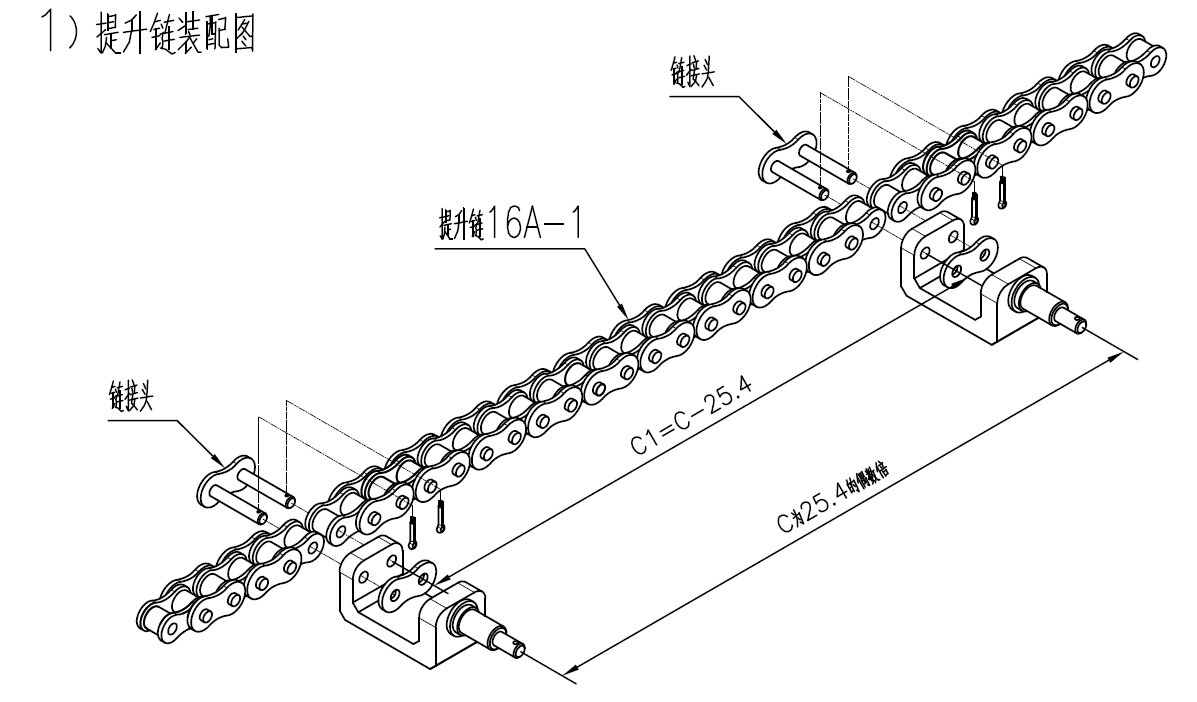
| Description Four column frame, standard mold column, standard L=2.5m, L < 2.5m; Standard modularization of each frame; Four chain lifting, chain specification 16a-1; Supporting plate chain specification: 16a-tb32; The drive is placed on the bottom frame of the hoist; Sealing box, the form of mesh, cooperate to connect with clip nut; Cooperate with roller table machine;
|
Type
| |
Name | Description |
Delivery length L (mm) | L=300~1000(If 600 < L 1000, the frame shall be non-standard) |
Carrier width W (mm) | W=200~1000(If 500 < W 1000, the frame shall be non-standard) |
Delivery height H (mm) | H≤800 |
Lower jaw height D(mm) | D≥700(Or dig a hole) |
Top and top height J(mm) | J≥H+150+122 |
Movements itinerary E(m) | E≤20(E=50*n≥C,N is a positive integer) |
Length of inlet conveyor F(mm) | F≥L+250(brake or block of inlet conveyor belt) |
Length of equipment L1 (mm) | L1=1510(Standard generalized) |
The device width W1 (mm) | W1=1075(Standard generalized) |
Equipment height H zero H 0 (mm) | H0=D+E+J |
Floor opening size (mm) | (L1+200)*(W1+200) |
The pit size (mm) | (L1+450)*(W1+350) |
Embedded iron dimension (mm) | (L1+380)* 600 |
Motor power P (kw) | E≤8m,P=1.5B; 8m<E≤12m,P=2.2B; |
Delivery speed V(m/min) | V≤40 |
Load per plate chain M(Kg) | M≤50 |
Plate chain length B(mm) | B=787.4(Otherwise, B > L+180 and B is an odd multiple of 25.4) |
Plate spacing C(mm) | C≥B+H+120 and C is an even multiple of 25.4 |
Plate A wide A(mm) | A=570(If not, then A≥W+100, round) |
Lift link length X(mm) | Xmin=2E+2B+900,Xmax= Xmin+300 X is an even multiple of 25.4 |
Number of chain plates Z | Xmin/C<Z<Xmax/C,Z = positive integer (when the efficiency is satisfied, Z is the minimum value) |
Delivery efficiency vertical η | η≤60000*V/C,η<2000件/小时 |
Total load (Kg) | 310Kg/m+550Kg |
Structure diagram:
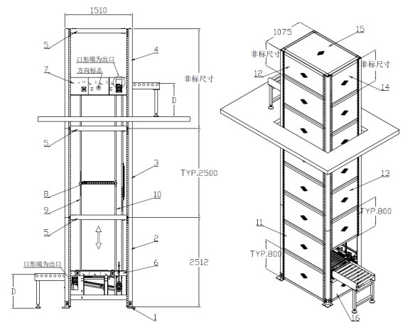
Order number | Name | Order number | Name |
1 | adjusting support | 11 | Standard side mesh of CZVC |
2 | Weld the bottom column | 12 | non-standard side mesh |
3 | standard frame column | 13 | standard end mesh |
4 | non-standard frame columns | 14 | non-standard mesh |
5 | middle ring beam assembly | 15 | top mesh |
6 | bottom frame component | 16 | gateway mesh |
7 | top frame component | 。。。 | The rest of the mesh is designed in the same way |
8 | Z-plate chain (see details at the end of this article) | ||
9 | Outside lifting chain | ||
10 | Inside lifting chain | ||
Note: the top frame has direction mark, pay attention when installing. | |||
Type C continuous hoist (cvc-c) :
| Description Four column frame, standard mold column, standard L=2.5m, L < 2.5m; Standard modularization of each frame; Four chain lifting, chain specification 16a-1; Supporting plate chain specification: 16a-tb32; The drive is placed on the bottom frame of the hoist; Sealing frame: in the form of mesh, use clip nut to fit and connect; Cooperate with roller table machine; |
Type
| |
Standard | Standard |
Delivery length L (mm) | L=400~1000(If 600 < L 1000, the frame shall be non-standard) |
Carrier width W (mm) | W=200~1000(If 500<W≤1000,the frame shall be non-standard) |
Delivery height H (mm) | H=≤500 |
Lower jaw height D(mm) | D≥700(Or dig a hole) |
Top and top height J(mm) | J≥H+150+272 |
Movements itinerary E(m) | E≤20(E=50*n≥H+B+200,N is a positive integer) |
Length of inlet conveyor F(mm) | F≥L+250(Entrance conveyor belt brake or block) |
Length of equipment L1 (mm) | L1=1660(Standard generalized) |
The device width W1 (mm) | W1=1075(Standard generalized) |
Equipment height H zero H0 (mm) | H0=D+E+J |
Floor opening size(mm) | (L1+200)*(W1+200) |
The pit size(mm) | (L1+450)*(W1+350) |
Embedded iron dimension(mm) | (L1+380)* 600 |
Motor power P (kw) | E≤8m,P=1.5B; 8m<E≤12m,P=2.2B; |
Delivery speed V(m/min) | V≤30 |
Load per plate chain M(Kg) | M≤50 |
Plate chain length B(mm) | B=787.4(Otherwise, B > L+180 and B is an odd multiple of 25.4) |
Plate spacing C(mm) | C≥2B+H+500 and C is an even multiple of 25.4 |
Plate A wide A(mm) | A=570(If not, then A≥W+100, round) |
Lift link length X(mm) | Xmin=2E+6B+2000,Xmax= Xmin+300 X is an even multiple of 25.4 |
Number of chain plates Z | Xmin/C<Z<Xmax/C,Z = positive integer (when the efficiency is satisfied, Z is the minimum value) |
Delivery efficiency vertical η | Vertical 60000*V/C, vertical < 2000 PCS/h |
Total load (Kg) | 310Kg/m+860Kg |
Structure diagram:
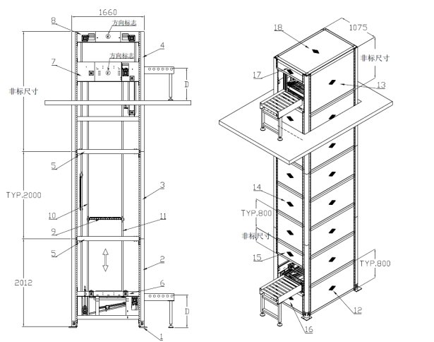
Order number | Name | Order number | Name |
1 | adjusting support | 11 | Inside lifting chain |
2 | Weld the bottom column | 12 | Inside lifting chain |
3 | standard frame column | 13 | Inside lifting chain |
4 | non-standard frame columns | 14 | standard end mesh |
5 | middle ring beam assembly | 15 | non-standard mesh |
6 | bottom frame component | 16 | gateway mesh |
7 | top frame component | 17 | outlet screen |
8 | top redirection frame component | 18 | top mesh |
9 | Type C carrier chain (see details at the end of this article) | 。。。 | The rest of the mesh design the same way |
10 | Outside lifting chain | ||
Note: each frame component should pay attention to the direction sign and install in the same direction on the same side. See the end of the article for details. | |||
Attachment: chain plate, rounding
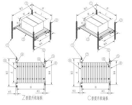
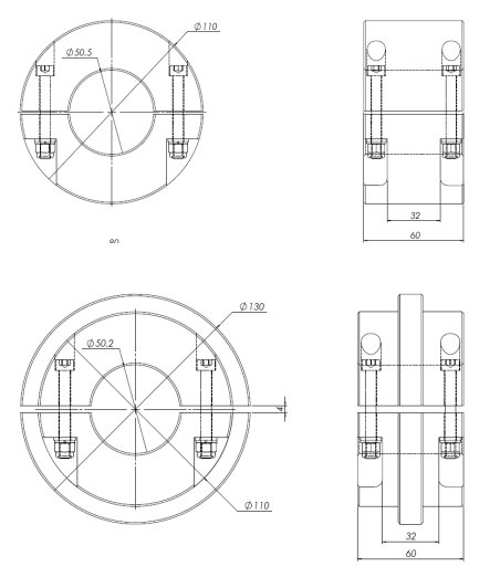
Chain roller details:
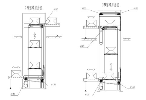
Size diagram of roller at each position:
Note: the diameter of the plate chain roller at the top exit position is 110. Please do not use the larger roller, otherwise it will interfere. The rest are using phi 130 large roller. The model is as follows:
Interface roller table and cover allowance:
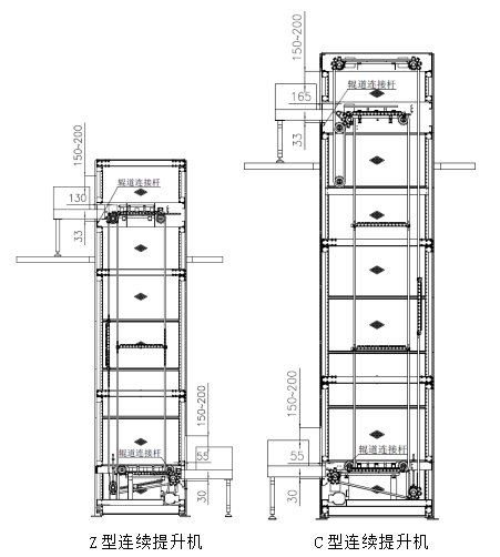
The serial number | Name of size | Z type continuous hoist | Type C continuous hoist |
1 | Lower roller table penetration | 85(cutting bevel of roller table 110) | 85(cutting bevel of roller table 110) |
2 | Allowance for lower roller table height | 30 | 30 |
3 | Upper roller table penetration | 160(cutting bevel of roller table 185) | 145 |
4 | Allowance for upper roller table height | 33 | 33 |
5 | Height clearance of the interface mesh | H+150~H+200 | H+150~H+200 |
Note: H is cargo height. The dimension of serial number 1.3 corresponds to the outer side of each column, the dimension of 2.4 corresponds to the roller table connecting the transverse file of each frame, and the dimension of 5 corresponds to the height of the roller surface of the roller table machine. | |||
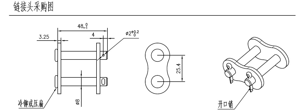
Chain assembly details:
Frame installation direction:
Name of the framework | Attached drawing | note |
Z bottom frame |
| |
Z top frame |
| According to the export and the up and down direction sign installation direction |
C bottom frame |
| |
Type C top frame and top redirection frame |
| Direction signs in accordance with the export and determine the installation direction, up and down in half an arrow mark, need to be same direction installation on the same side. |